
Kenick SM-PS-I: A Smarter, More Reliable Approach to CATV Power Supply Status Monitoring
Reduce installation complexity, eliminate an unnecessary RF drop cable, and add surge protection for critical broadband equipment.
Reliable status monitoring is an important part of maintaining today's broadband networks. When a CATV power supply experiences a problem, status monitoring helps operators identify the issue and respond appropriately. But how the status monitoring device connects to the network can affect installation costs, long-term reliability, and the risk of costly service interruptions.
One common approach is to run a separate RG6 drop cable from a nearby tap to the power supply cabinet to provide the RF path for the status monitoring modem. While this approach can work, it introduces additional materials, installation steps, connections, and potential failure points.
The Kenick SM-PS-I (aka SMPSI) offers an alternative. By combining the functions of the SPI/PIM, tap, and power inserter into one device installed inside the power supply cabinet, the SM-PS-I carries RF and power over the existing hardline power cable. The result is a simplified RF path, reduced installation complexity, and 6 kV of surge protection designed to protect both the status monitoring device and the power supply.
Two Approaches to Status Monitoring
Traditional installation: A separate RF drop
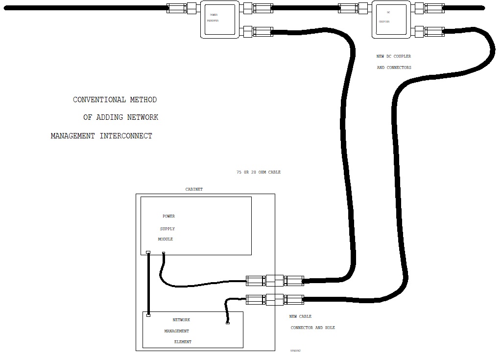
The conventional approach uses an additional cable to establish the RF path between the HFC network and the status monitoring device inside the power supply cabinet. This requires additional connectors, a cabinet bulkhead fitting, an in-line drop surge protector, and installation labor.
Industry-accepted drop lengths are typically in the range of 150–300 feet, depending on the application and installation conditions. Even when a nearby tap is within range, the additional cable introduces potential failure points that must be considered over the life of the installation.
Kenick SM-PS-I: An integrated solution
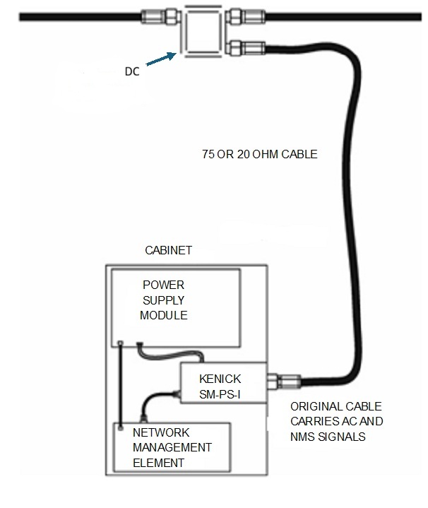
The Kenick SM-PS-I resides inside the power supply cabinet and carries RF and power over the existing hardline power cable. A short drop jumper inside the cabinet connects the status monitoring device to the tap incorporated into the SM-PS-I.
This eliminates the need for a separate external RF drop while providing 6 kV of surge protection designed to protect both the status monitoring modem and the power supply.
The difference is straightforward: instead of adding another cable to the outside plant, the SM-PS-I integrates the required functions into the existing power supply arrangement.
The Hidden Cost of a Separate Drop Cable
When a tap is located close enough to a power supply cabinet, installing a separate drop cable may seem like a straightforward and economical solution. However, the initial installation cost is only part of the equation.
Consider the estimated materials and labor required to install an aerial RG6 drop with a minimum 60% braid:
| Item | Estimated cost |
|---|---|
| Two drop connectors | $0.78 |
| Bulkhead connector assembly | $15.00 |
| RG6 coaxial cable allowance | $30.00 |
| In-line drop surge protector | $7.00 |
| Aerial installation labor | $25.00 |
| Total estimated installation cost | $77.78 |
These figures are illustrative estimates. Actual costs will vary with cable length, braid percentage, material pricing, and local labor rates.
An estimated $77.78 may seem reasonable for an individual installation. But the cable and its connections must continue to perform over time in an outdoor environment, and any repair may require a technician to return to the site.
Depending on the MSO's cost model, a truck roll can cost $200 or more. A single drop-related repair can therefore exceed the original installation cost several times over. For operators managing hundreds or thousands of power supply cabinets, even occasional repairs can become a meaningful operating expense.
Drop-Cable Reliability: Potential Failure Points to Consider
A properly installed and maintained drop cable can provide reliable service. The objective is not to suggest that drop cables are inherently unreliable, but to recognize that an additional cable and its connections introduce potential failure points that must be managed.
Connector preparation and installation matter
Compression connectors require proper cable preparation, appropriate tools, and correct installation technique. Potential causes of connector problems include:
- Incorrect dielectric length, dielectric that is not flush, or dielectric that is out of round.
- Incorrect center conductor length, adhesive on the center conductor, or a scored center conductor.
- Center conductor not properly cleared of the foil or braid.
- Incorrect braid length.
- An incorrect or poorly maintained cable preparation tool.
- Improper use of the compression tool.
- Incorrect installation of the port seal or use of an incorrect port seal.
- A loose connector.
- Improper messenger removal, where applicable.
These are potential issues, not guaranteed failures. A qualified technician using the correct materials and tools can avoid many of these problems. Nevertheless, each step introduces an opportunity for an installation error that could compromise the connection.
Environmental conditions add another layer of risk
Even a properly installed drop cable must withstand the conditions of the outside plant throughout its service life. Potential hazards include:
- Wind and repeated line vibration.
- Ice and snow loading.
- Falling tree limbs and other physical impacts.
- Corrosion at connector and port interfaces.
- Mechanical stress that weakens the cable or its connections over time.
A failure is not inevitable, but environmental exposure can damage a cable or connection that was functioning properly when installed. These issues can be particularly challenging when they occur during severe weather, when technicians may already be responding to multiple network problems.
The cost of a failed drop goes beyond the cable
When a drop cable fails, the cost may include troubleshooting, technician dispatch, replacement materials, and repair labor. A failed RF path may also interrupt status monitoring, making it more difficult for an operator to monitor the power supply remotely.
The in-line drop surge protector typically used in this arrangement is intended to protect the status monitoring device on the RF path. It does not provide the same protection to the power supply itself. This distinction is important because a power supply failure can have consequences far beyond the cost of repairing a cable.
The Kenick SM-PS-I: Simplifying the RF Path
The Kenick SM-PS-I was designed to eliminate the need for a separate external RF drop to provide status monitoring connectivity.
It combines the SPI/PIM, tap, and power inserter functions into one device installed inside the power supply cabinet. RF and power are carried over the existing hardline power cable, while a short drop jumper inside the cabinet connects the status monitoring device to the tap incorporated into the SM-PS-I.
This integrated design offers several practical advantages.
1. Eliminate the separate external RF drop
By using the existing hardline power cable for both RF and power, the SM-PS-I removes the need to install an additional aerial cable between a nearby tap and the power supply cabinet.
This eliminates the associated drop-cable materials, field-installed connectors, and external cable exposure for that RF path. It also removes the potential failure points associated with that separate cable, including connector preparation issues, compression errors, weather-related damage, and physical impacts.
2. Simplify installation
The SM-PS-I is designed to fit into the normal power supply cabinet installation process. The labor required to install the SM-PS-I is virtually no different from the labor required to connect the power cable to the cabinet from the power inserter. When an MSO installs the equipment, the labor is comparable to installing the SPI or PIM.
For new construction, a directional coupler is used instead of the power inserter. Because these components cost approximately the same, the change does not represent a significant additional component expense.
If the MSO purchases a preassembled power supply cabinet, the cabinet manufacturer can install the SM-PS-I before delivery, further simplifying field deployment. In either scenario, the SM-PS-I avoids the additional work associated with installing a separate aerial RF drop.
3. Provide 6 kV of surge protection
The SM-PS-I provides 6 kV of surge protection designed to protect both the status monitoring modem and the power supply.
Electrical disturbances can enter the HFC network through a variety of mechanisms, including ground potential rise and line-drop overload conditions. Surges reaching the power supply cabinet through the RF network can put connected equipment at risk.
The SM-PS-I incorporates a sacrificial protection approach. If a surge exceeds the unit's suppression capability, the SM-PS-I is designed to sacrifice itself to help protect the more costly power supply and status monitoring equipment.
No surge protection device can eliminate every electrical risk or guarantee that equipment will never be damaged. However, incorporating protection into the RF interface provides an additional layer of defense for critical broadband infrastructure.
4. Make replacement straightforward
If a severe surge damages the SM-PS-I, replacing it is designed to be a straightforward process. The unit can be replaced without cutting away heat-shrink tubing from the hardline cable and connector or removing the hardline connector from the cabinet and SPI/PIM assembly.
Under appropriate field conditions, replacement can take approximately two minutes. That design can reduce the time and effort required to restore the monitoring connection after a major surge, while avoiding unnecessary disturbance of the existing hardline cable and connector assembly.
Comparing the Two Approaches
| Consideration | Separate drop cable | Kenick SM-PS-I |
|---|---|---|
| RF path | Requires a separate external drop | Uses the existing hardline power cable |
| Additional aerial cable | Required | Not required |
| Field installation | Requires drop installation and connections | Labor comparable to SPI/PIM installation |
| Potential drop-related failures | Connector, workmanship, weather, and physical damage risks | Eliminates the separate external RF drop and its associated risks |
| Surge protection | Typical in-line drop protector protects the monitoring device, not the power supply | 6 kV protection designed for both the monitoring device and power supply |
| Replacement after a major surge | Depends on the components damaged and repair required | Designed for approximately two-minute replacement |
Understanding the Cost Comparison
The SM-PS-I has an approximate product cost of $210. For an existing installation requiring a directional coupler faceplate change, the additional estimated cost is $15, bringing the combined component cost to approximately $225.
At first glance, this is more than the estimated $77.78 required to install a separate drop cable. However, the comparison needs to account for installation labor, the different equipment configurations, and potential future repair costs.
Existing installations
For an existing installation, the SM-PS-I and faceplate represent an estimated $225 investment, compared with $77.78 for the separate drop installation. The initial difference is approximately $147.22, before accounting for any differences in installation labor.
If the separate drop subsequently requires a repair costing $200 or more, the conventional approach's cumulative cost rises to at least $277.78. That exceeds the $225 SM-PS-I and faceplate cost by $52.78, although the comparison excludes any additional SM-PS-I installation costs not already accounted for.
This example illustrates how a single drop-related truck roll can change the financial comparison. Actual savings will depend on repair frequency, local labor rates, installation conditions, and the MSO's accounting practices.
New construction
New construction presents a different comparison. The directional coupler replaces the power inserter at approximately the same component cost, and the SM-PS-I's installation labor is comparable to the labor already required to install the SPI or PIM. The SM-PS-I can also be pre-installed by the cabinet manufacturer.
In this scenario, the key advantage is avoiding the additional materials and labor for a separate external RF drop, while integrating the monitoring connection and surge protection into the cabinet design.
For both new and existing installations, the long-term financial assessment should include potential maintenance costs and the consequences of equipment failure—not simply the initial component price.
The Business Cost of a Prolonged Outage
The financial consequences of a power supply failure can extend well beyond a replacement component or a technician's visit. If a surge damages a power supply and interrupts service, the MSO may incur additional costs associated with troubleshooting, emergency repairs, customer support, and restoration of service.
Depending on the duration and circumstances of the outage, applicable service agreements, and company policies, the MSO may also need to issue subscriber statement credits. Commercial customers can be particularly significant because their service agreements may involve higher recurring fees or specific service-level commitments.
The potential business impact can include:
- Replacement of damaged power supplies and related equipment.
- Technician dispatches, troubleshooting, and repair labor.
- Lost monitoring visibility while the status monitoring connection is unavailable.
- Potential residential subscriber credits.
- Potential commercial customer credits.
- Additional operational demands on network maintenance and customer support teams.
The actual financial impact will depend on the number of customers affected, the duration of the outage, the services involved, and the MSO's contractual obligations and policies.
The SM-PS-I cannot guarantee that outages or customer credits will be avoided. Its value is that it provides surge protection designed to protect both the status monitoring device and the power supply, while eliminating the separate external RF drop and its associated failure risks.
When evaluating protection for outside plant equipment, the relevant question is not just what a component costs. It is also what an equipment failure could cost the network and its customers.
A Simpler Approach to Broadband Network Reliability
Broadband operators continually look for ways to reduce operating expenses, simplify field installations, and protect critical network equipment.
The Kenick SM-PS-I brings these objectives together by combining the functions of the SPI/PIM, tap, and power inserter into one cabinet-mounted device. It carries RF and power over the existing hardline power cable, eliminating the need for a separate external RF drop for status monitoring.
The result is a simplified installation, fewer potential failure points associated with a separate drop, and 6 kV of surge protection designed to protect both the status monitoring device and the power supply.
The bottom line: A separate drop cable can provide a workable RF path, but it introduces additional materials, installation steps, environmental exposure, and potential maintenance costs. The Kenick SM-PS-I offers a more integrated approach—one designed to simplify status monitoring connectivity, reduce drop-related risks, and help protect critical broadband equipment.
To learn more about the Kenick SM-PS-I and its role in CATV power supply status monitoring, visit Kenick.com.
Questions?
Contact Kenick to learn more about the SM-PS-I and surge protection for broadband network equipment.